In many specialized environments such as data centers, telecommunications hubs, electrical substations, engine rooms, and archival facilities, traditional water-based fire suppression systems simply aren't feasible due to the sensitive nature of the equipment and materials present. Instead, these critical spaces rely on advanced gas fire suppression systems to swiftly and effectively combat fires while minimizing damage.
A gas fire suppression system stores fire extinguishing agents in specialized pressure vessels, releasing them as gases when triggered by fire detection systems. These systems come in various forms, each tailored to specific needs and environments. Options include heptafluoropropane, IG541 mixed gas, high-pressure carbon dioxide, and water mist systems, each offering unique advantages and applications.
Key components of a gas fire suppression system include storage cylinders and valves for the extinguishing agent, starting cylinders, area selection valves (in pipe network combined distribution systems), pressure switches, nozzles, gas fire suppression controllers, smoke detectors, temperature sensors, manual fire alarm buttons, audible and visual fire alarms, and manual control devices. These components work in harmony to swiftly detect and suppress fires, safeguarding valuable assets and personnel.
Moreover, the integration of gas fire suppression controllers with automatic fire alarm systems enhances efficiency and response times. Utilizing protocol buses, these controllers communicate seamlessly with fire control rooms, providing real-time feedback on system actions and ensuring swift, coordinated responses to fire incidents.
In essence, gas fire suppression systems offer a vital layer of protection in environments where traditional water-based systems fall short, enabling proactive fire safety measures tailored to the unique challenges of modern industrial and technological facilities.
-
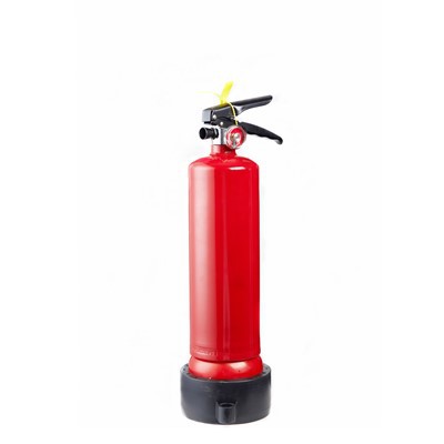
![Fm 200 Portable Fire Extinguisher]() Fm 200 Portable Fire Extinguisher
Fm 200 Portable Fire ExtinguisherIntroducing our FM200 Portable Fire Extinguisher – the ultimate solution for swift and effective fire suppression. Engineered with precision and designed for reliability, our extinguisher offers...
-
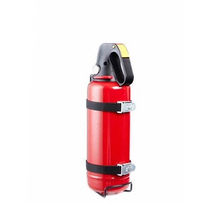
![FM200 Flooding System]() FM200 Flooding System
FM200 Flooding SystemIntroducing our Fm200 Flooding System, a revolutionary fire suppression solution that redefines safety and protection in critical environments. Inspired by the efficiency of traditional fire...
-
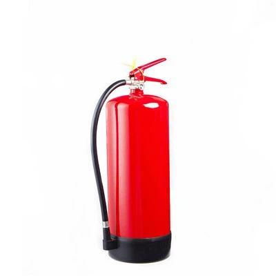
![Fm 200 Gas System]() Fm 200 Gas System
Fm 200 Gas SystemIntroducing our Fm 200 Gas System: a cutting-edge fire suppression solution. With its rapid response, eco-friendly design, and non-conductive properties, it swiftly extinguishes fires while...
-
![Fm 200 Fire Extinguishing System]() Fm 200 Fire Extinguishing System
Fm 200 Fire Extinguishing SystemThe Fm 200 Fire Extinguishing System represents a pinnacle in fire suppression technology, offering unparalleled protection against fire hazards in diverse environments. Engineered with...
-
![Fm 200 Fire Alarm System]() Fm 200 Fire Alarm System
Fm 200 Fire Alarm SystemThe Fm 200 Fire Alarm System is an efficient and reliable fire detection and alarm solution designed to protect various places from fire hazards. The system uses advanced technology and reliable...
-
![Fm 200 Clean Agent Fire Suppression System]() Fm 200 Clean Agent Fire Suppression System
Fm 200 Clean Agent Fire Suppression SystemThe FM200 Clean Agent Fire Suppression System is a state-of-the-art solution meticulously designed to protect your critical assets from fire hazards. Engineered with cutting-edge technology, this...
-
![Fire Fm 200 System]() Fire Fm 200 System
Fire Fm 200 SystemThe FM200 Fire Suppression System is a state-of-the-art solution engineered to provide swift and effective protection against fire hazards. With its cutting-edge technology and innovative design,...
-
![Clean Agent System Fm200]() Clean Agent System Fm200
Clean Agent System Fm200Our Clean Agent System Fm200 is engineered to provide unparalleled protection for your valuable assets in the face of fire emergencies. This cutting-edge solution boasts a range of features and...
-
![Clean Agent Fire Suppression System Fm200]() Clean Agent Fire Suppression System Fm200
Clean Agent Fire Suppression System Fm200Our FM200 Clean Agent Fire Suppression System stands as a pinnacle of innovation and reliability in safeguarding critical assets against fire hazards. Tailored to meet the stringent demands of...


China fm 200 fire fighting system manufacturer
Choose the plan that suits you best.
fM200 fire protection system
In many specialized environments such as data centers, telecommunications hubs, electrical substations, engine rooms, and archival facilities, traditional water-based fire suppression systems simply aren't feasible due to the sensitive nature of the equipment and materials present. Instead, these critical spaces rely on advanced gas fire suppression systems to swiftly and effectively combat fires while minimizing damage.
clean agent fire suppression system fm200
Key components of a gas fire suppression system include storage cylinders and valves for the extinguishing agent, starting cylinders, area selection valves (in pipe network combined distribution systems), pressure switches, nozzles, gas fire suppression controllers, smoke detectors, temperature sensors, manual fire alarm buttons, audible and visual fire alarms, and manual control devices. These components work in harmony to swiftly detect and suppress fires, safeguarding valuable assets and personnel.

fm200 gas fire suppression system
A gas fire suppression system stores fire extinguishing agents in specialized pressure vessels, releasing them as gases when triggered by fire detection systems. These systems come in various forms, each tailored to specific needs and environments. Options include heptafluoropropane, IG541 mixed gas, high-pressure carbon dioxide, and water mist systems, each offering unique advantages and applications.
fm 200 fire extinguishing system
Moreover, the integration of gas fire suppression controllers with automatic fire alarm systems enhances efficiency and response times. Utilizing protocol buses, these controllers communicate seamlessly with fire control rooms, providing real-time feedback on system actions and ensuring swift, coordinated responses to fire incidents.
|
ENGINEERED SYSTEM DATA |
|||
|
Model |
QMQ4.2/90N-JM |
QMQ4.2/120N-JM |
QMQ4.2/150N-JM |
|
Cylinder Capacity (L) |
90 |
120 |
150 |
|
Max. Working Pressure (MPa) |
5.3 |
||
|
Storage Pressure (MPa) |
4.2 |
||
|
Working Temperature Range |
0~50°C (System room); -10°C (Min Temp. in protection area) |
||
|
Charging Rate (Kg/m³) |
≤950 |
||
|
Air actuating Pressure (MPa) |
6.0 |
||
|
Operating Voltage (V) |
AC220 |
||
|
Back-Up Power (V) |
DC24 |
||
|
Discharging Time (S) |
≤10 |
||
|
System Startup Method |
Automatic / manual / emergency operation |
||
|
Approval & Standard |
ISO9001-2015 |
||
HFC-227ea shall not be used on fire involving the following materials unless they have been tested and recognized:
Certain chemicals or mixtures of chemicals, such as cellulose nitrate and gunpowder, that are capable of rapid oxidation in the absence of air.
Reactive metals such as lithium, sodium, potassium, magnesium, titanium, zirconium,uranium and plutonium.
Metal hydrides.
Chemicals capable of undergoing auto-thermal decomposition, such as certain organic peroxidase and hydrazine.
STORAGE CYLINDERS: The storage cylinders must be kept in an upright position and securely fixed during transportation. The storage cylinders is not allowed to roll or drag on the spot. Use trolleys, forklifts and other similar safe handling tools.
WARNING: The improper operation of the pressure storage cylinder is very dangerous and can cause violent discharge, personal injury and property loss. Before operating the product, the operator must undergo professional training
WARNING: If the outlet cap is lost, a new outlet cap must be found and installed on the outlet of the cylinder valve before removing the cylinder set.
WARNING: If these requirements are not followed, improper operation may cause serious personal injury, death and property damage.
WARNING: The fire extinguishing agent filled in this system will decompose to produce a certain amount of hydrogen fluoride gas when extinguishing the fire. The high concentration of hydrogen fluoride gas can cause injury to personnel. Before the fire extinguishing device releases the extinguishing agent, all personnel must evacuate the scene within the delay period. After the fire is extinguished, the exhaust gas must be discharged before the staff can enter the scene.
CAUTION
ThHFC-227ea is not effective on the following items:
industry-leading
Class A deep seated fires.
01
High market share
Class D combustible metals
02
High market share
Chemicals capable of auto-thermal decomposition
03
Perfect product system
Chemical capable of rapid oxidation.
04
Efficient after-sales service
Enclosures with hot surfaces >400℃.
05
why choose us
fm200 fire suppression system Overview
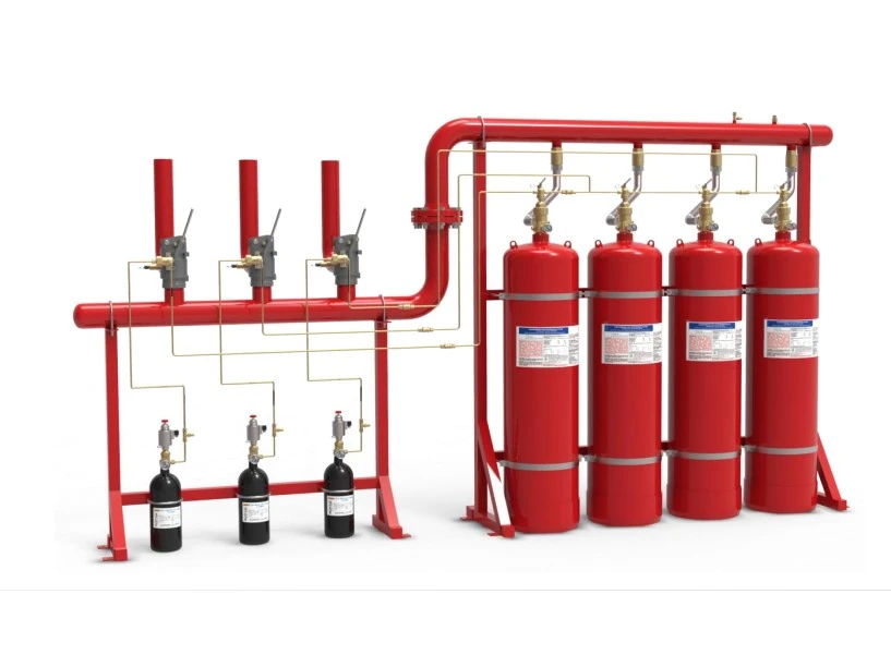
Utilizing HFC-227ea fire extinguishing agent, our engineered fire suppression system sets the standard for safety and environmental responsibility. This colorless and odorless agent boasts non-conductive properties and zero ozone depletion potential (ODP), aligning perfectly with stringent environmental regulations. With its exceptional fire suppression efficiency, minimal equipment impact, and rapid extinguishing capabilities, HFC-227ea stands as an ideal replacement for traditional halogenated alkane agents.
Our HFC-227ea automatic fire suppression system offers versatile control modes, including automatic, electrical manual, and mechanical emergency manual operation. The system comprises essential components such as an automatic alarm and fire control system, fire extinguishing agent cylinders, actuating cylinders, release devices, selection valves, check valves, nozzles, and piping systems. Adaptable to various application requirements, it can be configured as unit-independent systems or combined distribution systems, providing tailored fire protection solutions for single-zone and multi-zone environments.
This advanced system finds wide-ranging applications in critical facilities such as electronic computer rooms, telecommunications centers, underground projects, offshore oil platforms, libraries, archives, treasure vaults, and power distribution rooms. By delivering unmatched performance and reliability, our HFC-227ea fire suppression system ensures the utmost safety and security for your most valuable assets.
Not Just Traditional Cyber & Immigration Firm
The gas (HFC-227ea) filled in the pipe network type heptafluoropropane fire extinguishing device has good clean performance, network has low working pressure, small storage space, does not destroy the ozone layer, meets environmental protection requirements, and has characteristics of colorless, odorless, non-conductive, no secondary pollution, and fast and efficient fire extinguishing. It is an ideal substitute for halon fire extinguishing agent at this stage It is used to extinguish all types of fires A, B, and C.
Especially for some electrical and electronic equipment, communication facilities, flammable liquids and gases, and for other fire protection of high-value property, the device has no residue after spraying, has low toxicity of the agent, and can be used safely in places with people. The advantages are more prominent for places where people often work.


Not Just Traditional Cyber & Immigration Firm
FEATURES
Low concentration of HFC-227ea required means less visual obscurity and minimal risk to personnel.
Small quantity of agent discharged minimises over pressurisation of the protection area.
Max Safety for personnel due to low toxicity.
High effective with 10 second discharge time when used with automatic detection.
Prevent re-ignition as long as concentration levels.
Not Just Traditional Cyber & Immigration Firm
Bank Vaults
Libraries
Rare Book Stores
Electronic Data Processing
Telephone Exchange Studios
Communication Centre
Transformer and Switch Rooms
Control Rooms
Test Laboratories
Flammable Liquid Stores

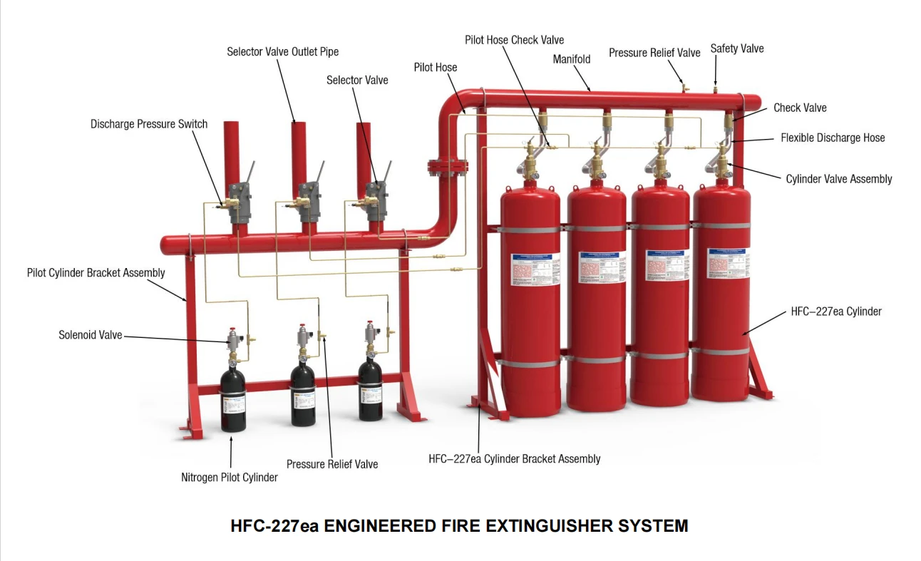
HFC-227ea ENGINEERED FIRE EXTINGUISHER SYSTEM
HFC-227ea Storage Cylinder
The HFC-227ea storage cylinder filled by JUNMO with HFC-227ea, and super-pressurised with dry nitrogen to 25 bar @ 21℃ (360 psi @ 70°F) and 42 bar @ 21℃ (600 psi @ 70°F).
JUNMO Agent Cylinders sharing the same manifold shall be equal in size and fill density. Cylinders are finished in red and are available in various sizes.
|
Volume |
Fill Capacity (kg) |
Nominal Working Pressure (MPa) |
Height |
Diameter |
Connection Thread |
|
|
Minimum |
Maximum |
|||||
|
90L |
43.2 |
100.8 |
5.3 |
1095 |
350 |
PZ56 |
|
120L |
57.6 |
134.4 |
5.3 |
1450 |
350 |
R2 |
|
150L |
72.0 |
168.0 |
5.3 |
1390 |
400 |
R2 |

Cylinder Valve Assembly
The cylinder valve is installed on the fire extinguishing agent cylinder kit to seal the fire extinguishing agent and actuating gas in the storage cylinder. In the event of a fire, the valve is usually opened by the actuating gas or electromagnetic device, and the actuating gas in the cylinder pushes the fire extinguishing agent. It is transported to the place where a fire occurs to extinguish the fire.
|
Model |
QRF32/5.3-JM |
QRF40/5.3-JM |
|
Diameter |
32mm |
40mm |
|
Working Pressure |
5.3 MPa |
5.3 MPa |
|
Cylinder Connection |
1.25’’ |
2’’ |
|
Actuator Connection |
M48X2 |
M60X2 |
|
Material |
Brass |
Brass |

Solenoid Valve (Actuating Cylinder Kit)
The solenoid valve is installed on the actuating cylinder kit to seal the actuating gas. In the event of a fire, the controller sends out a fire extinguishing command to activate the electromagnetic device to open the valve to release the actuating gas to open the corresponding selector valve and cylinder valve through the actuating pipeline to release the extinguishing agent and extinguishing fire.
|
Model |
RF5/6.6-JM |
|
Diameter |
6mm |
|
Working Pressure |
6.6 MPa |
|
Connection Thread |
PZ27.8 |
|
Rated Voltage |
DC24V |
|
Rated Current |
1.6A |
|
Rated Suction Force |
≥80 N |
|
Material |
Brass |

Selector Valve
The selector valve is usually closed. When a fire occurs, the actuating gas enters the selector valve actuating cylinder, pushes the piston in the cylinder, and opens the selector valve pressure arm through the action of the connecting rod mechanism. At this time, the selector valve is already in the open state. Then start the gas and open the cylinder valve, release the fire extinguishing agent, and send it into the protection area through the selector valve to implement fire extinguishing.

Pilot Hose Check Valve
The pilot hose check valve is installed in the actuating pipeline to control the flow direction of actuating gas. It is mostly used in combined distribution systems to realize the activation of corresponding devices in different protection zones.
|
Model |
QD5/6.6-JM |
|
Diameter |
5mm |
|
Working Pressure |
6.6 MPa |
|
Opening Pressure |
≤0.2 MPa |
|
Connection |
M14X1.5 |
|
Material |
Brass |

Check Valve
The check valve is installed between the manifold pipe and the flexible hose to control fire extinguishing agent from the flexible hose into the manifold pipe.
|
Model |
QYD32/8-JM |
QYD40/8-JM |
|
Diameter |
32mm |
40mm |
|
Working Pressure |
8.0 MPa |
8.0 MPa |
|
Opening Pressure |
≤0.2 MPa |
≤0.2 MPa |
|
Connection (M) |
M48X2 |
M60X2 |
|
Length (L) |
107 |
120 |
|
Thread (R) |
11/4 |
11/2 |
|
Material |
Brass |
Brass |

Discharge Pressure Switch
The discharge pressure switch is installed on the outlet pipe assembly downstream of selector valve in the combined distribution system, and on the header in the unit independent system. Release the extinguishing agent to make it act, and send a feedback signal to the fire extinguishing alarm controller to notify that the cylinder valve has been opened and that the extinguishing agent has been released to the corresponding protection zone.
|
Model |
XF0.6/17.2-JM |
|
Working Pressure |
17.2 MPa |
|
Opening Pressure |
0.6±0.06 MPa |
|
Rated Voltage |
DC24V |
|
Contact Rating |
0.5A 250VAC |
|
Connection |
R1/4 male |
|
Material |
Brass |

Safety Valve
The safety valve is installed on the manifold pipe. When the pressure in the pipeline is greater than the allowable value, the safety diaphragm bursts to protect the system.
|
Model |
QAX7.2-JM |
|
Release Pressure |
7.2±0.36 MPa |
|
Material |
Brass |

Pressure Relief Valve
DG0.3/17.2-JM pressure relief valve is installed in the actuating pipeline of each zone of the gas system. When there is a small amount of leakage in the actuating device (pressure in the pipeline ≤0.1 MPa), the leaked gas is discharged from the outlet port to avoid gas accumulation of boost pressure in the pipeline causes the system to malfunction.
When the system is working, due to the rapid increase of pressure in the actuating pipeline (≥0.5 MPa), the constant discharge pressure regulator will automatically shut down to ensure that the system starts normally.
|
Model |
DG0.3/17.2-JM |
|
Working Pressure |
17.2 MPa |
|
Closed Pressure |
0.3 MPa |
|
Connection |
M14X1.5 female |

Flexible Discharge Hose
The flexible discharge hose is installed between the cylinder valve and the check valve, so that the fire extinguishing agent can flow smoothly from the cylinder valve to the check valve.
|
Model |
Dia. |
W.P. |
L |
H |
D |
|
QRG32/5.3 |
32mm |
5.3MPa |
55mm |
450mm |
M48X2 female |
|
QRG40/5.3 |
40mm |
5.3MPa |
60mm |
550mm |
M60X2 female |

Nozzle
Nozzles are installed in the protection area to evenly spray and atomize the fire extinguishing agent to the protection area for fire extinguishing.
|
Model |
D |
L |
Connection |
|
QPT24/20-JM |
38mm |
42mm |
3/4’’ female |
|
QPT25/25-JM |
44mm |
47mm |
1’’ female |
|
QPT37/32-JM |
53mm |
50.5mm |
1 1/4’’ female |
|
QPT43/40-JM |
59mm |
55mm |
1 1/2’’ female |
|
QPT48/50-JM |
69mm |
60mm |
2’’ female |

Nitrogen Pilot Cylinder
The Nitrogen pilot cylinder is used to store the actuating gas. The actuating gas is nitrogen, and the filling pressure is 6.0MPa (20°C). When a fire occurs, the solenoid actuating cylinder valve opens, and the actuating gas passes through the actuating pipeline to open the corresponding selector valve and agent cylinder valve to release the extinguishing agent and implement the fire extinguishing.

BINET SYSTEM LAYOUT
The Xinhao Cabinet Type Fire Extinguishing System is a engineered fire extinguishing system,it is also as known as a pipeless fire extinguishing system. A complete Cabinet Type Fire Extinguishing System is composed of Cabinet,HFC-227ea storage cylinder,Cylinder Valve, Manual/Solenoid Actuator,Manual/Pneumatic Cylinder Valve,Flexible Discharge Hose,Discharge Pressure Switch,Nozzles,etc. The special design of the Cabinet Type Fire Extinguishing System doesn’t require pipes installation and cylinders storage room. The system can be locate in the protected area directly,when the fire happen, the HFC-227ea agent will be spray out directly to the protected area through the discharge nozzle,with very low pressure loss. Compare to the Piping extinguishing system,the Cabinet Type Fire Extinguishing system has following advantages:
More efficient
More economic
Easier Installation
Smaller locating space


|
SINGLE-CYLINDER CABINET DATA |
|||||
|
Model |
GQQ40/2.5-JM |
GQQ70/2.5-JM |
GQQ90/2.5-JM |
GQQ120/2.5-JM |
GQQ150/2.5-JM |
|
Cylinder Capacity |
40L |
70L |
90L |
120L |
150L |
|
Max. Protection Volume |
63 m³ |
127 m³ |
163 m³ |
217 m³ |
272 m³ |
|
Outline Dimension |
500x481x1450 |
500x481x1450 |
500x481x1600 |
500x481x1900 |
500x531x1900 |
|
Max. Working Pressure |
42 bar |
||||
|
Storage Pressure |
25 bar |
||||
|
Working Temperature Range |
0~50°C (System room); -10°C (Min Temp. in protection area) |
||||
|
Filling Ratio |
≤1.15 kg/L |
||||
|
Operating Voltage |
AC 220V |
||||
|
Back-Up Power |
DC 24V |
||||
|
Discharging Time |
≤10 sec |
||||
|
System Startup Method |
Automatic / manual / emergency operation |
||||
|
DOUBLE-CYLINDER CABINET DATA |
||||
|
Model |
GQQ70*2/2.5-JM |
GQQ90*2/2.5-JM |
GQQ120*2/2.5-JM |
GQQ150*2/2.5-JM |
|
Cylinder Capacity |
70L x 2 |
90L x 2 |
120L x 2 |
150L x 2 |
|
Max. Protection Volume |
326 m³ |
254 m³ |
326 m³ |
343 m³ |
|
Outline Dimension |
900x500x1450 |
900x500x1600 |
900x500x1900 |
1000x550x1600 |
|
Max. Working Pressure |
42 bar |
|||
|
Storage Pressure |
25 bar |
|||
|
Working Temperature Range |
0~50°C (System room); -10°C (Min Temp. in protection area) |
|||
|
Filling Ratio |
≤1.15 kg/L |
|||
|
Operating Voltage |
AC 220V |
|||
|
Back-Up Power |
DC 24V |
|||
|
Discharging Time |
≤10 sec |
|||
|
System Startup Method |
Automatic / manual / emergency operation |
|||

HFC-227ea Storage Cylinder
|
Model |
XF0.6/17.2-JM |
|
Working Pressure |
172 bar |
|
Opening Pressure |
6±0.6 MPa |
|
Rated Voltage |
DC24V |
|
Contact Rating |
0.5A 250VAC |
|
Connection |
R1/4 male |
|
Material |
Brass |

Discharge Pressure Switch
The Discharge Pressure Switch is installed on the Cylinder Valve,it is used to feedback information generated by the agent release pressure to tell the extinguishing control panel that system is opened, to indicate extinguishing agent released.The Discharge Pressure Switch can be resetting by pull out the Resetting Ball when the Cabinet type HFC-227ea extinguishing system is refilled after actuating.
|
Pressure (bar) |
||||
|
40L |
42 |
774 |
300 |
PZ56 |
|
70L |
42 |
940 |
350 |
PZ56 |
|
90L |
42 |
1140 |
350 |
PZ56 |
|
120L |
42 |
1440 |
350 |
R2 |
|
150L |
42 |
1405 |
400 |
R2 |

Cylinder Valve Assembly(1)
|
Data of Cylinder Valve |
||
|
Model |
QRF32/5.3-JM |
QRF40/5.3-JM |
|
Nominal Diameter |
32mm |
40mm |
|
Working Pressure |
42 bar |
42 bar |
|
Cylinder Connection |
PZ56 |
R²2 |
|
Actuator Connection |
M48X2 |
M60X2 |
|
Operation |
Manual or Automatic |
|

Cylinder Valve Assembly(2)
|
Data of Manual/Solenoid Actuator |
|
|
Model |
DQ85N-JM |
|
Power Supply |
DC 24V ±3 |
|
Rated Current |
1.6 A |
|
Current Duration |
100% |

Discharge Nozzle
|
Model |
Nominal Diameter |
Connection Thread |
E |
H |
Remark |
|
QPT37/32-JM |
DN32 |
Rc1 1/4’’ |
Φ65 |
38 mm |
For 40L, 70L, 90L Cylinder |
|
QPT43/40-JM |
DN40 |
Rc1 1/2’’ |
Φ74 |
45 mm |
For 120L, 150L Cylinder |

Precautions for installation and operation
1.1.The installation site of this system should meet the following requirements:
The ambient temperature between the storage cylinders is 0℃~+50℃; it should be kept dry and well ventilated;
The air should not contain explosive, conductive dust and corrosive harmful substances, otherwise the device should be protected;
A room that is easy for operators to approach, easy to enter and exit, and not easy to cause a fire. The door of the room should open outwards.
1.2.Personnel who install, debug and use this device should be familiar with the basic structure, working principle, performance and action process of this device, as well as the structure and working state of each valve.
1.3. In the process of transportation and installation, the cylinder group should avoid getting close to the heat source, and should be lightly loaded and unloaded to prevent collision, lying down, and upside down.
1.4. The frame of the fire extinguishing agent cylinder kit and the frame of the actuating gas cylinder kit shall be fastened by anchor bolts.
1.5. The solenoid actuating cylinder valve is equipped with a safety pin to prevent leakage or malfunction of the solenoid actuating cylinder valve due to collisions and vibrations during transportation, installation and debugging. After the installation is completed on site, the safety pin must be removed before putting it into use, otherwise the valve will not start and the system will fail.
1.6. After the cylinder kit is firmly installed on the fixed bracket, the outlet blocking cover can be removed. Before removing the cylinder kit from the piping during maintenance, install the outlet plugging cap on the movable cylinder kit above the outlet of the cylinder valve.
1.7. Non-professional trained personnel are not allowed to install and operate in order to avoid accidents.
1.8. Before the fire extinguishing device releases the fire extinguishing agent, all workers must evacuate the scene within the delay period. The extinguishing agent filled in this system will produce a certain amount of hydrogen fluoride gas when extinguishing the fire. High-concentration hydrogen fluoride gas can cause harm to personnel. After the fire is extinguished, the exhaust gas must be discharged before the staff can enter the scene.
System Operating Procedures
2.1 The operator should carefully read the instruction manual of this product and be familiar with related products.
2.2 This system equipment, together with the automatic alarm and fire extinguishing control system, forms a complete fire alarm and fire extinguishing system, which has three control modes: automatic, electrical manual, and mechanical emergency manual. It is recommended to use automatic control in unmanned protection areas and manual control in manned protection areas.
2.3 Before the fire extinguishing device releases the fire extinguishing agent, all personnel must be evacuated from the scene within the delay period. After the fire is extinguished, the exhaust gas must be discharged before the staff can enter the scene.
2.4 When mechanical emergency operation is required, the specific operation is as follows:
Unplug the solenoid-actuating cylinder valve in the desired fire-extinguishing area, and press the button down.
If the nitrogen in the actuating gas cylinder kit is not enough to open the cylinder valve on the cylinder kit, first press down the selector valve handle in the fire area, open the pressure arm, and then turn the handle on the cylinder valve to open the valve.
2.5 After the system implements fire extinguishing, the selector valve, pressure switch, check valve, cylinder valve, etc. should be reset in time, and relevant parts should be replaced.
2.6 Refill the fire extinguishing agent and nitrogen according to the requirements of the system engineering design.
2.7 After the inspection is ready, make the device in a normal working state.
2.8 Non-related personnel should be prevented from operating this system device to prevent accidents.
Use and maintenance instructions
Cylinder Valve Assembly (Agent Cylinder Kit)
3.1 When the valve needs to be opened manually, the valve can be opened only by turning the handle.
3.2 Installation of pressure gauge: The threaded interface at the end of the compression nut shown in the figure is the installation part of the pressure gauge. Put a nylon gasket on the surface of the thread root and tighten the pressure gauge with a wrench.
3.3 Pressure detection, pressure gauges are installed on the front of the cylinder valve, which can display the pressure in the storage cylinder. When the pressure indicated value is lower than the green zone, it should be refilled.
3.4 When filling the fire extinguishing agent and driving gas, remove the pressure gauge, connect the end to the fire extinguishing agent hose, and loosen the compression nut to fill.
3.5 The cylinder valve is equipped with a safety diaphragm to prevent the pressure in the fire extinguishing agent cylinder group from being too high, and to release the pressure to protect the safety of the storage cylinder. Under normal circumstances, the safety diaphragm will not move. Only under abnormal conditions (such as high filling pressure and high ambient temperature), it may burst. After the safety diaphragm is activated and the pressure of the storage cylinder is released, the safety diaphragm should be replaced immediately, a tightness test should be carried out, and the fire extinguishing agent should be refilled.
Solenoid Valve (Actuating Cylinder Kit)
4.1 The cylinder valve is equipped with a safety pin (as shown in the figure above) to prevent the valve from malfunctioning due to collisions and vibrations during transportation, installation and commissioning, which may cause leakage or malfunction of the cylinder valve. After the installation is completed on site, the safety pin must be withdrawn before being put into use, otherwise the valve will not start and the system will fail.
4.2 A safety diaphragm (diaphragm burst pressure 9MPa) is installed on the cylinder valve to prevent excessive internal pressure from releasing pressure to protect the safety of the storage cylinder. The diaphragm should be replaced after the diaphragm moves and the pressure of the storage cylinder is released.
4.3 The cylinder valve has two opening modes: electric start and mechanical manual. For electric start, the controller sends out the valve opening command to make the electromagnetic actuating device act and open the cylinder valve; the mechanical manual is to manually remove the plug and press the button down to open the cylinder valve.
4.4 The cylinder valve is equipped with a pressure gauge to display the starting gas pressure in the cylinder. When the pressure indicated value is lower than the green zone, the starting gas should be refilled.
Solenoid Valve (Actuating Cylinder Kit)
4.1 The cylinder valve is equipped with a safety pin (as shown in the figure above) to prevent the valve from malfunctioning due to collisions and vibrations during transportation, installation and commissioning, which may cause leakage or malfunction of the cylinder valve. After the installation is completed on site, the safety pin must be withdrawn before being put into use, otherwise the valve will not start and the system will fail.
4.2 A safety diaphragm (diaphragm burst pressure 9MPa) is installed on the cylinder valve to prevent excessive internal pressure from releasing pressure to protect the safety of the storage cylinder. The diaphragm should be replaced after the diaphragm moves and the pressure of the storage cylinder is released.
4.3 The cylinder valve has two opening modes: electric start and mechanical manual. For electric start, the controller sends out the valve opening command to make the electromagnetic actuating device act and open the cylinder valve; the mechanical manual is to manually remove the plug and press the button down to open the cylinder valve.
4.4 The cylinder valve is equipped with a pressure gauge to display the starting gas pressure in the cylinder. When the pressure indicated value is lower than the green zone, the starting gas should be refilled.
Selector Valve
5.1 When it is necessary to open the valve manually, press down the handle and open the pressing arm to open the selector valve.
5.2 After the selector valve is actuated, it should be manually reset and checked for abnormal conditions before it can continue to be used.
Pilot Hose Check Valve
When installing, pay attention to the start gas flow direction indicated by the arrow.
Check Valve
When installing, pay attention to the flow direction indicated by the arrow.
Discharge Pressure Switch
When the signal feedback device is activated, the reset ball head is pulled out. After resetting, you can continue to use it.
Safety Valve
After use, the safety diaphragm should be replaced. The replaced safety diaphragm should be the same as the original material model, shape, size, and thickness, and be a qualified product.
Relevant industry knowledge
What is FM200 fire suppression?
FM 200 is a clean agent fire suppressant that works by removing the heat from the fire triangle (oxygen, heat, and fuel). It is a colorless, odorless, and electrically non-conductive gas that leaves no residue to clean up. It is safe for use in occupied spaces and for the ozone layer.
What is the difference between FM200 and CO2?
CO2, a colourless and odourless fire suppression agent, falls into the category of gaseous fire suppression, offering a clean agent solution. On the other hand, FM200, also known as HFC-227ea, is a synthetic fire suppression agent known for its efficiency in rapidly extinguishing fires while leaving minimal residue.
What is the difference between FM200 and clean agent fire suppression system?
Unlike FM 200 systems, the agent is stored as a liquid and is converted into a gas when discharged. This clean agent is a replacement for halon and an alternative to hydrofluorocarbon extinguishing agents so it's not subject to the HFC phaseout.
Is FM200 gas harmful to humans?
Clean agent systems using FM-200™ are non-toxic to humans in levels used for extinguishing fires. When designing a fire suppression system, particular emphasis is placed on accurately calculating clean agent concentration levels to be safe in occupied spaces. Because it is clear, it will not obscure your vision.
Is FM200 a gas or foam?
FM200 is a non-flammable gas used for fire suppression. It doesn't damage electronic products, used correctly it's safe for people to breathe in and can be used in an enclosed space, making it ideal for colocation data centres.
Does fm200 leave a residue?
FM-200 is a clean agent fire suppressant for Class A, B, and C fires. It's a colorless, non-toxic gas that leaves no residue. For these reasons, it's an ideal solution for protecting high-value assets in areas that are occupied and in locations where the cleanup of other agents is problematic.
Which type of fire-suppression system is the safest for humans?
Are Fire Suppression Systems Harmful to Humans?
Inert Gas Fire Suppression Systems
When designed within appropriate criteria, these systems are people-safe and approved for normally-occupied rooms. Inert gasses are ideal for environments that house sensitive equipment such as server rooms or industrial facilities with CNC machines.
We're well-known as one of the leading fm200 fire suppression system manufacturers and suppliers in China for our quality products and good service. Please feel free to buy custom made fm200 fire suppression system at competitive price from our factory.