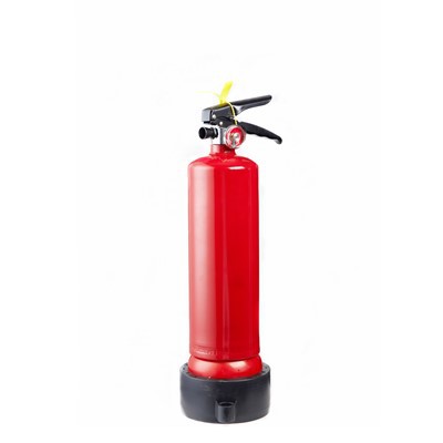
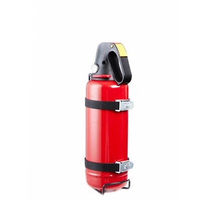
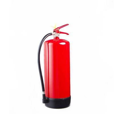
A fire hose reel is a fixed firefighting device designed to provide a controlled supply of water through a hose that can be manually deployed toward a fire. Unlike a portable fire extinguisher, a hose reel is connected to a building's water supply, allowing the operator to access a continuous water flow while the supply system maintains the required hydraulic conditions.
The working principle is relatively simple:
However, the reel itself contains several mechanical components that determine how the hose is stored, deployed, rotated, and rewound. The interaction between the hydraulic and mechanical systems is what makes a fire hose reel practical for fixed fire-protection installations.
What Is the Working Principle of a Fire Hose Reel?
A fire hose reel combines two functions:
- Mechanical hose management - storing and deploying the hose in a controlled manner.
- Hydraulic water delivery - transferring water from a fixed supply pipe through the hose to the nozzle.
When the system is ready for use, the hose remains wound around the reel drum. The water connection is connected to the building's fire-water supply.
During an emergency, the operator typically:
- Opens the cabinet or accesses the reel.
- Pulls the hose toward the fire.
- Allows the reel drum to rotate as the hose is withdrawn.
- Opens the water-control valve, according to the system configuration.
- Directs the nozzle toward the fire.
- Controls the water stream at the nozzle.
The reel therefore does not generate water pressure by itself. The building's water supply provides the hydraulic pressure; the reel provides controlled hose storage and deployment.
Main Components of a Fire Hose Reel
Understanding the components makes the operating principle easier to visualize.
| Component | Primary Function |
|---|---|
| Reel drum | Stores the hose in controlled coils |
| Frame/bracket | Supports the reel assembly |
| Spindle/shaft | Provides the rotational axis |
| Swivel/rotary joint | Allows water transfer while the reel rotates |
| Hose | Carries water to the fire |
| Hose guide | Controls hose movement during deployment |
| Isolation/control valve | Controls water supply |
| Nozzle | Directs and regulates the water stream |
| Hose stopper | Limits the hose's fully retracted position |
| Spring mechanism | Automatically rewinds the hose on spring-driven models |
| Cabinet | Protects the assembly and provides an accessible installation point |
Not every fire hose reel uses exactly the same mechanical arrangement. The internal design depends on whether the reel uses manual rewinding, spring-assisted rewinding, or another mechanism.
How Water Reaches the Fire Hose
The hydraulic side of the system begins with the building's water supply.
A simplified flow path is:
The pressure available at the hose reel installation must overcome several forms of resistance, including:
- pipe friction;
- hose friction;
- fittings;
- elevation difference;
- nozzle resistance;
- flow requirements.
Therefore, the actual performance of a fire hose reel cannot be determined from the reel alone.
A reel may have a particular hose diameter and nozzle configuration, but the available water flow depends on the complete hydraulic system.
How Does the Reel Rotate?
The hose is wrapped around a cylindrical drum.
When the operator pulls the hose outward, the pulling force creates a rotational moment around the reel shaft.
The reel rotates as the hose leaves the drum.
For a spring-driven reel, this rotation also winds the internal spring mechanism. The stored mechanical energy can subsequently be used to rotate the drum in the opposite direction and rewind the hose.
For a manually rewound reel, the operator rotates a handle or crank to return the hose to the drum.
How Does a Spring-Driven Fire Hose Reel Work?
Spring-driven reels use a preloaded mechanical spring to provide automatic hose retraction.
The operating sequence can be represented as:
The spring is normally connected mechanically to the reel drum.
As the operator pulls the hose out:
Drum rotation → spring winding → mechanical energy storage
When the hose is released or the operator allows retraction:
Stored spring energy → drum rotation → hose rewinding
The spring must provide sufficient torque across the useful hose length.
This is important because the required torque changes as the hose position changes and as the effective winding radius changes.
Why Is Spring Torque Important?
Spring torque is one of the most important mechanical characteristics of an automatic hose reel.
If the spring torque is too low:
- the hose may not retract completely;
- the final section may remain loose;
- hose coils may become disorganized;
- rewinding may become inconsistent.
If the spring torque is excessive:
- retraction may become unnecessarily aggressive;
- the hose may move too quickly;
- the operator may have difficulty controlling retraction;
- mechanical loads on the reel assembly may increase.
A properly designed spring mechanism therefore needs to balance:
This is one reason why the spring should be matched to the specific reel and hose configuration rather than selected independently.
How Does a Manual Fire Hose Reel Work?
A manual fire hose reel does not use stored spring energy for automatic rewinding.
Instead, the operator rotates a handwheel or crank connected to the reel shaft.
The basic process is:
Manual reels are mechanically straightforward and can be useful where:
- hose deployment is relatively infrequent;
- automatic retraction is unnecessary;
- the hose is relatively long or heavy;
- the installation favors direct mechanical control.
The main difference from a spring-driven reel is the source of the rewinding force.
| Feature | Spring-Driven Reel | Manual Reel |
|---|---|---|
| Hose deployment | Manual | Manual |
| Rewinding | Spring-assisted/automatic | Hand-operated |
| Energy source | Mechanical spring | Operator |
| Retraction control | Controlled by mechanism | Controlled directly by operator |
| Mechanical complexity | Higher | Lower |
| Operator effort during rewinding | Lower | Higher |
What Does the Swivel Do?
The swivel, or rotary water connection, solves an important mechanical problem.
The reel drum needs to rotate, but the water-supply connection remains stationary.
Without a rotary connection, continuous hose rotation would place torsional stress on the fixed water pipe or hose connection.
The swivel provides a rotating interface between the stationary water supply and the rotating reel.
Conceptually:
The swivel must therefore perform two functions simultaneously:
- allow rotational movement;
- maintain a sealed water passage.
Its sealing elements must withstand the system's operating pressure, temperature, and water conditions.
A worn swivel can cause:
- leakage;
- increased rotational resistance;
- water loss;
- difficult reel movement;
- premature component failure.
How Does the Hose Leave the Reel?
The hose does not simply slide directly from the drum.
Many reel designs incorporate a hose guide or outlet guide to control the hose's direction.
The guide helps:
- reduce rubbing against the cabinet;
- maintain a controlled withdrawal angle;
- distribute hose movement;
- reduce localized bending;
- improve rewinding alignment.
This becomes increasingly important when the hose reel is installed inside a cabinet.
The cabinet opening, hose guide, reel position, and hose bend radius should be treated as one mechanical system.
Why Is Drum Diameter Important?
Drum diameter affects how the hose bends and how it is stored.
When the hose is wrapped around a drum, it experiences bending stress. A smaller drum generally creates a tighter bend.
The reel must be compatible with the hose's minimum recommended bend radius.
An undersized drum can create excessive bending and may contribute to:
- hose deformation;
- increased resistance during deployment;
- accelerated hose wear;
- difficulty in rewinding;
- reduced service life.
The drum also determines how much hose can be stored.
How Is the Hose Wound onto the Drum?
Proper winding is not simply about putting the hose back onto the reel.
The hose should form controlled layers across the drum width.
During rewinding, the reel and hose guide work together to prevent:
- random overlapping;
- localized stacking;
- excessive gaps;
- hose pinching;
- uneven distribution.
On automatic reels, the spring provides the rotational force while the operator or guide controls the hose path.
If the hose is repeatedly rewound at an incorrect angle, the resulting coil pattern can become uneven.
This can eventually affect reel capacity and deployment.
What Happens When the Hose Is Fully Deployed?
A properly configured reel is designed around a defined hose length.
As the hose approaches full extension:
- the available hose length decreases;
- the remaining hose stays on the drum;
- the operator reaches the intended operating range.
A hose stopper or similar mechanism may be used to define the retracted position or manage the hose's end location.
The reel should not be treated as a mechanism that can safely accommodate unlimited hose length.
Both hose capacity and drum geometry must be established during selection.
How Does the Nozzle Control Water?
The nozzle converts the water flow inside the hose into a directed discharge.
Its geometry influences:
- discharge pattern;
- flow rate;
- velocity;
- effective reach;
- operator control.
Depending on the system design, the nozzle may provide different discharge modes, such as a more concentrated stream or a broader spray pattern.
The nozzle should therefore be considered part of the hydraulic design rather than simply an accessory attached to the hose end.
Fire Hose Reel Hydraulic Performance
The performance of a hose reel is determined by several hydraulic parameters.
Important factors include:
Available supply pressure − system losses = pressure available at the nozzle
This is why simply specifying a hose reel's maximum pressure does not prove that the installation will deliver the required firefighting performance.
How Does Hose Diameter Affect Operation?
Hose internal diameter directly affects hydraulic resistance.
For a given flow condition, reducing the internal diameter can significantly increase friction losses.
At the same time, a larger hose may:
- carry more water;
- increase hose weight;
- require a larger reel;
- increase storage volume;
- require greater retraction torque.
This creates an engineering trade-off.
| Hose Characteristic | Smaller ID | Larger ID |
|---|---|---|
| Water-carrying capacity | Lower | Higher |
| Friction loss at comparable flow | Generally higher | Generally lower |
| Hose weight | Lower | Higher |
| Reel capacity requirement | Lower | Higher |
| Retraction load | Lower | Higher |
The correct diameter therefore depends on the required hydraulic performance and reel design.
Why Does Hose Length Matter?
A longer hose increases the physical coverage area around the reel but also changes the mechanical and hydraulic requirements.
Increasing hose length can result in:
- higher hose weight;
- greater reel capacity requirements;
- greater drum dimensions;
- greater spring torque requirements;
- increased friction loss;
- greater operator pulling distance.
For example, simply replacing a standard hose with a substantially longer hose without checking reel capacity and spring torque can cause poor rewinding performance.
The hose length should therefore be specified together with the reel.
Fire Hose Reel Working Cycle
The complete mechanical and hydraulic cycle can be summarized as follows.
The hose is fully wound around the drum. The water system is connected to the reel according to the installation design.
The operator opens the cabinet or accesses the exposed reel.
The operator pulls the hose toward the fire. The drum rotates while the hose leaves the reel.
The appropriate valve/nozzle controls the water discharge.
Water travels continuously through the hose while the operator directs the nozzle.
After use, the hose is returned to the reel. On a spring-driven model, stored spring energy rotates the drum. On a manual model, the operator rotates the crank.
The hose is rewound and the equipment is returned to its designated position for future use.
What Happens Inside the Reel During Operation?
A simplified mechanical sequence for a spring-driven reel looks like this:
↓
Drum Rotates
↓
Spring Is Tensioned
↓
Hose Extends
↓
Water Flows Through Rotary Connection
↓
Operator Uses Nozzle
↓
Hose Is Released/Returned
↓
Spring Releases Stored Energy
↓
Drum Rotates in Reverse
↓
Hose Rewinds
This illustrates an important point: the mechanical and hydraulic systems operate simultaneously but perform different functions.
The spring does not generate the water flow.
The water pressure does not rewind the hose.
Each system has its own role.
Common Fire Hose Reel Mechanical Problems
Understanding how a reel works also makes common problems easier to diagnose.
| Problem | Possible Cause |
|---|---|
| Hose does not retract fully | Insufficient spring torque, excessive hose weight, friction |
| Reel is difficult to rotate | Bearing, swivel, alignment, or mechanical resistance |
| Hose comes out unevenly | Poor winding, guide misalignment |
| Hose rubs against cabinet | Incorrect outlet position or cabinet clearance |
| Water leaks at rotating connection | Swivel seal or connection problem |
| Hose is difficult to pull | Excessive friction, poor reel alignment, tight bending |
| Hose capacity is insufficient | Incorrect drum/hose combination |
| Retraction is too aggressive | Excessive spring torque or incorrect spring selection |
| Hose develops kinks | Poor storage, bending, guide arrangement |
| Cabinet obstructs hose movement | Incorrect cabinet/reel integration |
A good troubleshooting process should examine the complete assembly rather than replacing the reel immediately.
How Does a Fire Hose Reel Cabinet Affect Reel Operation?
When a hose reel is installed inside a cabinet, the cabinet becomes part of the mechanical operating environment.
Three dimensions are particularly important:
If these are poorly matched, the hose may contact:
- cabinet edges;
- door frames;
- hinges;
- hose outlets;
- surrounding building structures.
This creates additional resistance during deployment and retraction.
For this reason, a fire hose reel cabinet should provide adequate clearance around the reel and maintain a smooth hose exit path.
Fire Hose Reel vs Portable Fire Extinguisher
A hose reel and portable extinguisher operate according to fundamentally different principles.
| Feature | Fire Hose Reel | Portable Fire Extinguisher |
|---|---|---|
| Water source | Fixed water supply | Stored extinguishing agent |
| Operating duration | Dependent on water supply | Limited agent quantity |
| Hose | Connected to fixed reel | Usually short discharge hose |
| Deployment | Pull hose from reel | Carry unit to fire |
| Mechanical storage | Reel drum | No rotating storage drum |
| Primary medium | Commonly water | Water, foam, powder, CO₂, etc. |
| Installation | Fixed location | Portable |
A hose reel is therefore best understood as a fixed water-delivery device with integrated hose management, rather than simply a larger extinguisher.
Key Parameters That Determine How a Fire Hose Reel Works
For engineers and purchasers, the following parameters should be evaluated together.
| Parameter | Mechanical/Hydraulic Effect |
|---|---|
| Hose length | Determines coverage, capacity and retraction load |
| Hose ID | Influences flow resistance |
| Hose OD | Influences reel capacity |
| Drum diameter | Determines hose bending geometry |
| Drum width | Determines storage capacity |
| Working pressure | Defines hydraulic operating conditions |
| Nozzle type | Influences discharge characteristics |
| Spring torque | Determines automatic retraction |
| Swivel specification | Enables rotating water transfer |
| Hose guide | Controls deployment and rewinding |
| Mounting orientation | Affects reel movement and hose path |
| Cabinet clearance | Influences deployment |
| Ambient temperature | Affects hose, seals and reel components |
| Corrosion environment | Determines material and coating requirements |
How to Select a Fire Hose Reel Based on Its Working Principle
Selection should begin with the required firefighting function rather than the reel's external appearance.
A practical sequence is:
Determine the required flow and pressure conditions according to the applicable fire-protection design.
Specify:
- hose ID;
- hose OD;
- length;
- pressure rating;
- temperature range;
- bend characteristics.
Check:
- drum capacity;
- drum diameter;
- mounting orientation;
- swivel;
- hose guide;
- rewind mechanism.
Verify:
- internal dimensions;
- hose outlet;
- door opening;
- mounting method;
- environmental protection.
Confirm that the water supply, pipework, valve, reel, hose, nozzle, and cabinet work together as one system.
Conclusion
A fire hose reel works by combining fixed water delivery with controlled mechanical hose storage.
The water supply provides the hydraulic energy required to discharge water. The reel drum allows the hose to be stored compactly and deployed by pulling it outward. A swivel enables the drum to rotate while maintaining the water connection, while a hose guide controls the hose path. On spring-driven models, the reel stores mechanical energy during deployment and uses that energy to rewind the hose after use. Manual models rely on a hand-operated crank for rewinding.
The most important engineering relationships are:
Therefore, evaluating a fire hose reel solely by hose length or external dimensions is insufficient. Hose diameter, drum geometry, spring torque, swivel construction, nozzle characteristics, cabinet clearance, and the available water supply must all be considered as part of the same fire-protection system.